6v6 Push Pull Amp Schematic IOT Wiring Diagram
PP2012 - KT88 Hi-End Push Pull Amplifier. PP2012 - 25 -35 W Extreme Hi - End Push Pull Amplifier. THIS IS NOT A COMMON PUSH-PULL! - very low feedback only 16dB. - low distortion near to 0.3 - 0.4%. - good damping factor near to transistor amp. - no electrolytic capacitors. started on March 10 st , 2012.
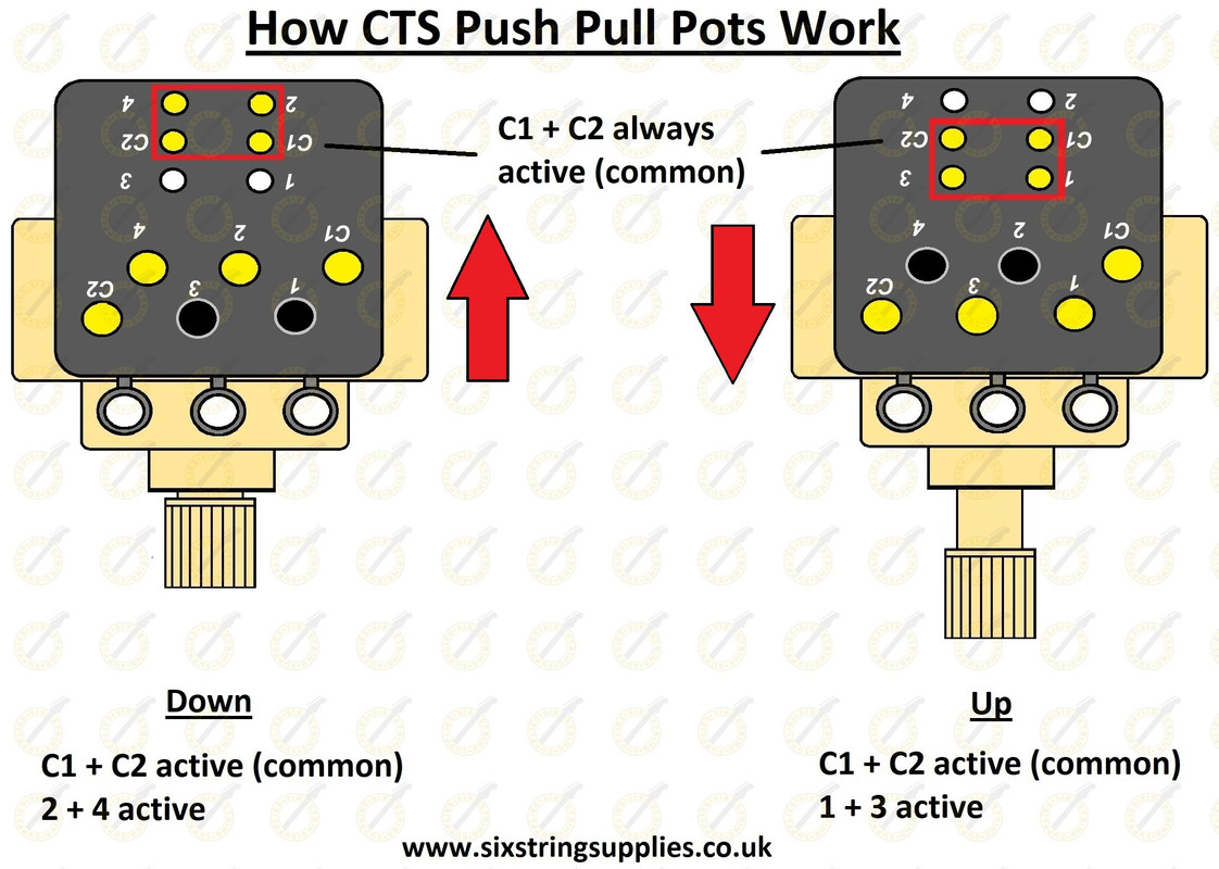
Push Pull Switch Wiring Diagram Wiring Diagram and Schematic Role
A push-pull amplifier is a type of electronic circuit that uses a pair of active devices that alternately supply current to, or absorb current from, a connected load. This kind of amplifier can enhance both the load capacity and switching speed.

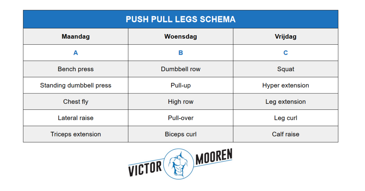
Push Pull Legs schema + Gratis 3/6daags schema!
MOSFET Push Pull Amplifier This is the AQA version closing after June 2019. Visit the the version for Eduqas instead. To gain access to revision questions, please sign up and log in. AS and A2: MOSFET BJ Transistor Class A Amplifier AS A2 a Uses drive loudspeakers amplify radio frequency energy before feeding to the antenna drive DC motors.

Een Push Pull schema voor 3 of 4 dagen per week
These deals - sometimes known as push, pull, or drag events - are called minimum trade-in allowances, and they can cost you big time if you're not careful. Vehicles have a trade-in allowance and an actual cash value (ACV) based on factors such as depreciation, resale value, and cost to replace. The trade-in allowance and ACV won't.

26Schéma de principe d'un amplificateur pushpull. Download Scientific Diagram
Push-Pull Amplifier is a power amplifier which is used to supply high power to the load. It consists of two transistors in which one is NPN and another is PNP. One transistor pushes the output on positive half cycle and other pulls on negative half cycle, this is why it is known as Push-Pull Amplifier.
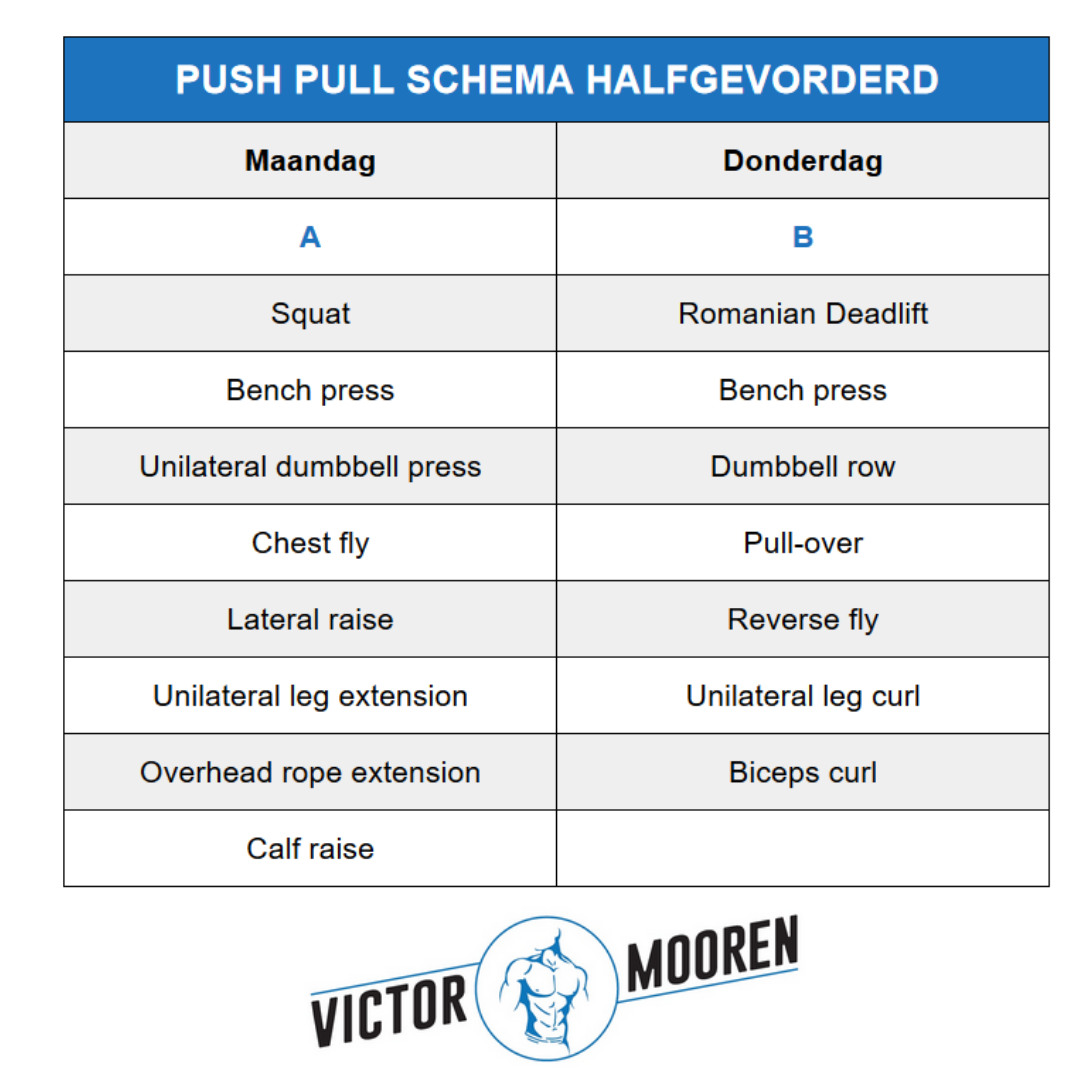
Alles wat je moet weten over een push pull schema Victor Mooren
The push-pull EL84 tube amplifier schematic is from the book "Build your own Audio Valve Amplifiers" by Rainer zur Linde. Push-Pull (PP) EL84 Tube Amplifier Schematic 5751 SRPP / EL84 (6BQ5) Self-Inverting Push-Pull Tube Amplifier ECC802S SRPP / EL84 (6BQ5) Self-Inverting Push-Pull Tube Amplifier

Push, Pull, Legs! Push, Pull, Legs is one of the best splits out their in my opinion. Largely
Push it, Pull it, or Drag Your Trade-In: seriously, as long as the owner possesses title and registration we will accept ALL vehicles regardless of condition. We have even accepted motorcycles, boats, and trailers! Show me the Money: a maximum trade-in allowance is applied towards the purchase of a vehicle. That could mean up to $3,500 towards.

The push/pull/legs split ( PPL) are one of the most simple and proven workout schedules around
#1 I buyed on ebay PCB Push-pull amplifier for EL34/KT88, as attached photos, whitout schematic. A friend have this schematic? Thx Attachments pcb1.jpg 117.6 KB · Views: 586 pcb2.jpg 106 KB · Views: 578 Demonkleaner Member Joined 2012 2021-10-17 8:29 pm #2 I'd message the ebay vendor for the schematic. They are usually pretty responsive E enziano

Push Pull Legs Workout Routine For Beginners for Build Muscle Fitness and Workout ABS Tutorial
See updated schematic at https://youtu.be/IZ3mP4PyTeoActive devices used are LM358 dual op amp, BD139 (NPN) & BD140 (PNP), and two 1N4004 general purpose d.

PushPull (PP) EL84 Tube Amplifier Schematic (ECC83 input)
Een Push-Pull trainingsschema voor 4 dagen per week Bouw binnen no-time spierkracht op. Door Redactie Men's Health Gepubliceerd op: 20/01/2020 Corey Jenkins // Getty Images Push en pull dagen.

Push Pull Legs schema + Gratis 3/6daags schema!
Power Supply Schematic - KT120 Push-Pull (PP) Tube Amplifier. Layout of the KT120 push-pull amplifier is uncritical and point to point wiring is fine. The circuit can be rewired for all 6 volt heaters if desired. An alternative that allows 6 volt driver tubes is to series a 20 ohm 10 watt resistor in series with the driver heater.

Follow me leanbellytips for more Fitness and Nutrition tips!!... in 2020 Push pull legs, Push
Fundamentally, a push-pull circuit uses a pair of effectively separate transistors operating 180O out of phase with one another. If good amplitude and phase balance is maintained between the signals in each half of the device, then an RF ground will exist at the midpoint. This approach leads to several advantages over single-ended designs:

ShredSupplements Push workout, Workout splits, Push pull legs workout
Apr 8, 2021 at 11:48 by "shortcut" I think you mean a short circuit, and if the second graph is current, those spikes suggest you have one. The trick is to turn one device OFF before turning the other ON; modify the driver circuit to do that. - user16324
Alles wat je moet weten over een push pull schema Victor Mooren
Now I can say without a doubt in my mind that my scratch built 6L6 Push Pull Stereo Tube Amplifier is finally complete with proper voltages and all!! All recycled parts. Stuff I found in parts boxes, ect. I paid nothing for the sound this amp puts out!. new solder boards to redo the entire power supply with Newer Capacitors with properly.

Pin by Daniela on full body workout Push pull legs, Muscle groups to workout, Push pull workout
The basic schema of a push-pull amplifier stage is depicted in Figure 20. It is composed of two vacuum tubes having an identical configuration and circuitry. The primary of the push-pull output transformer has a centre tap that receives the V+ voltage. Anodes of the two vacuum tubes are connected to the two ends of the output transformer primary.
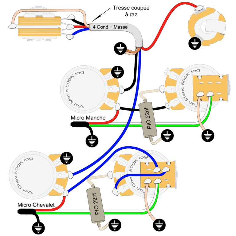
Plan câblage LesPaul® push pull split Guitar N' Blues le blog
Mullard EL34 Push-Pull Tube Amp Schematic with Dynaco A420 Transformers This is the improved Push-Pull Mullard EL34 tube amplifier circuit. The amplifier circuit shown uses the Dynaco A420 audio output transformers which have a primary impedance of 6600 ohms. the schematic is from the Dynaco Super Fidelity Output Transformers catalog.